How to Un-Brick your Toshiba Chromebook 2 (Gandof) without invoking any demons

So, i was trying to install custom firmware on my girlfriend's Toshiba Chromebook 2 CB-35 2015 (i3 processor), also known as "Gandof". Overall it's a very good machine for a reasonable price, but the bundled Chrome OS can be limited depending on your use case and preferences.
So, i tried to install the custom ROM provided by Matt: https://mrchromebox.tech/
It seems most of the time it works, but for some reason, when i rebooted, black screen, no response of any type to input. Booting from USB didn't work, plugging and unplugging didn't either... now i had to explain to my girlfriend her computer was now a pretty brick with the shape of a notebook.
So, let's not panic now, if you are in the same situation, there is a way out. Opening the case, if you have a magnifying glass or eagle eyes, you can read the numbers of the BIOS chip, something that looks like this
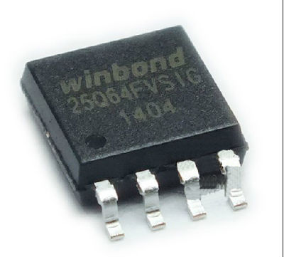
That little dot there is important, but more on that later. The thing we screwed up when flashing, was this little chip, which holds the BIOS, the program that runs even before our operating system starts, we overwrote it with something that for some reason was corrupt. I understand there is more than one way to rewrite it, but i will explain here the one that worked perfectly for me.
Required materials
I contacted MrChromebox (Matt DeVillier) who kindly explained to me what i needed to do, i had already read some articles, which i'll put at the end.
This is not the only way to flash a ROM, but as far as i know, it is one of the cheapest and easiest. Even if you don't have the exact same materials, maybe with some research you can reach the same results (I found no tutorials exactly for my case, but i mangled together many of similar situations and reached the right answer, so i hope this is true for you too even if you don't have the same materials/computer/bios/etc)
You can download this rom which i extracted from the recovery image or extract it yourself with this guide
I used:
Configure the Raspberry
First of all, just in case, update your raspberry pi's firmware with sudo rpi-update and reboot.
Then, you should configure Raspbian to enable SPI, which is the interface we can use to flash the BIOS. To do this, execute the command sudo raspi-config which will open a menu like this:
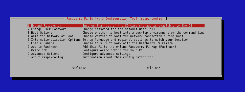
Choose 9 Advanced Options
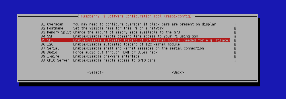
Choose A5 SPI and enable SPI
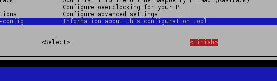
Finish the configuration to save it
Check on the console that you have the flashrom program available, if you don't, and like me you don't find it with apt-get install (Why? i don't know) you can install it like this:
sudo apt-get install pciutils libftdi-dev libusb-dev libpci-dev libusb-1.0
git clone https://github.com/stefanct/flashrom.git
cd flashrom
make
sudo make install
Make sure you can now call the command flashrom
Then you can shutdown the Pi and disconnect it from power. Try also having the new ROM to flash already in the Pi before you proceed to make it less stressful later on.
Know your chip
The BIOS chip inside the Toshiba Chromebook 2 (Gandof) is a W25Q64FV. This chip has the following pinout:
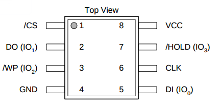
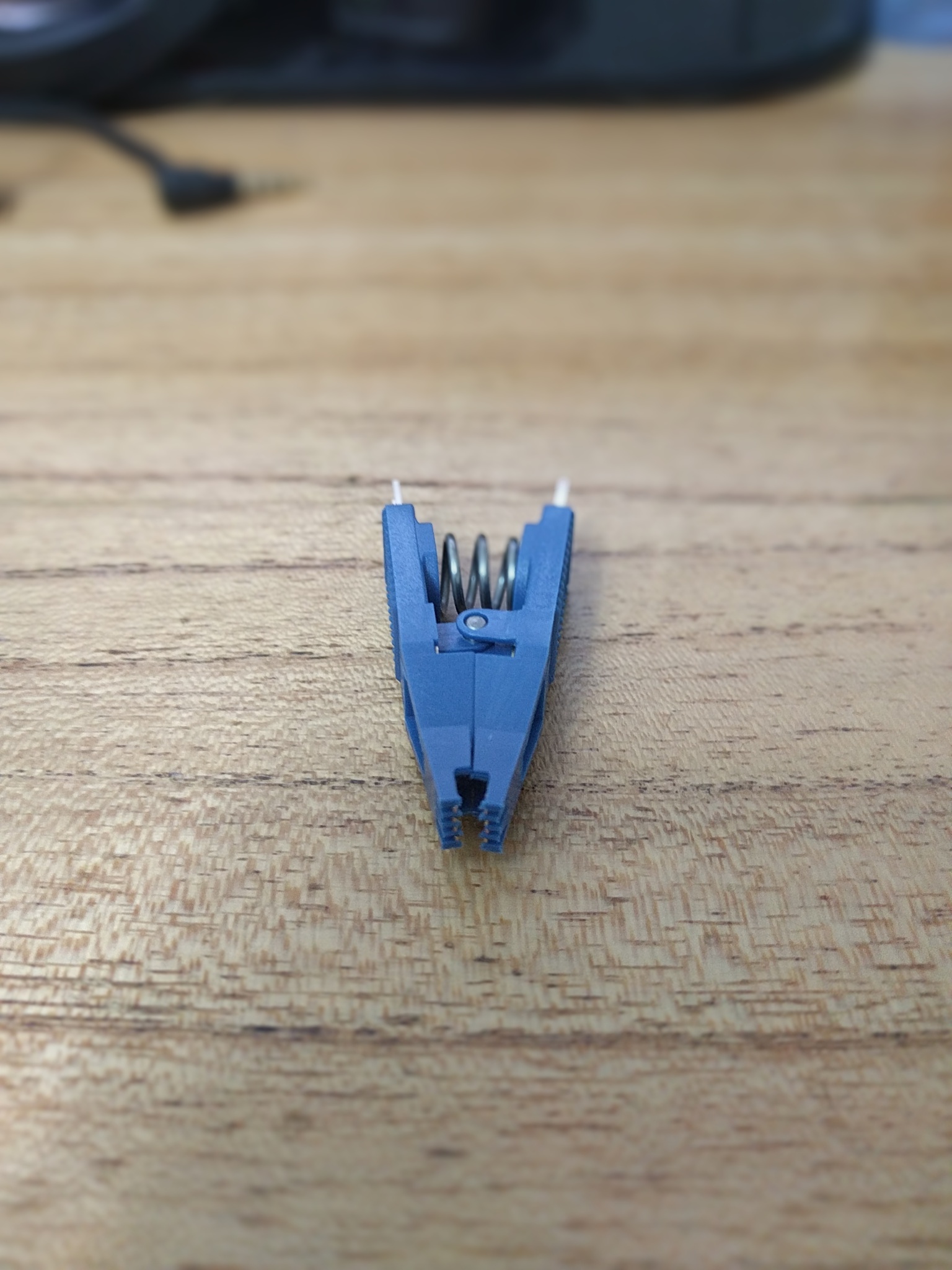
The gray dot on the schema is actually visible in the chip, that's useful to know which position to put the clip on,very important! We won't be connecting the wires to the BIOS, but to the pins on top of the test clip, bear that in mind.
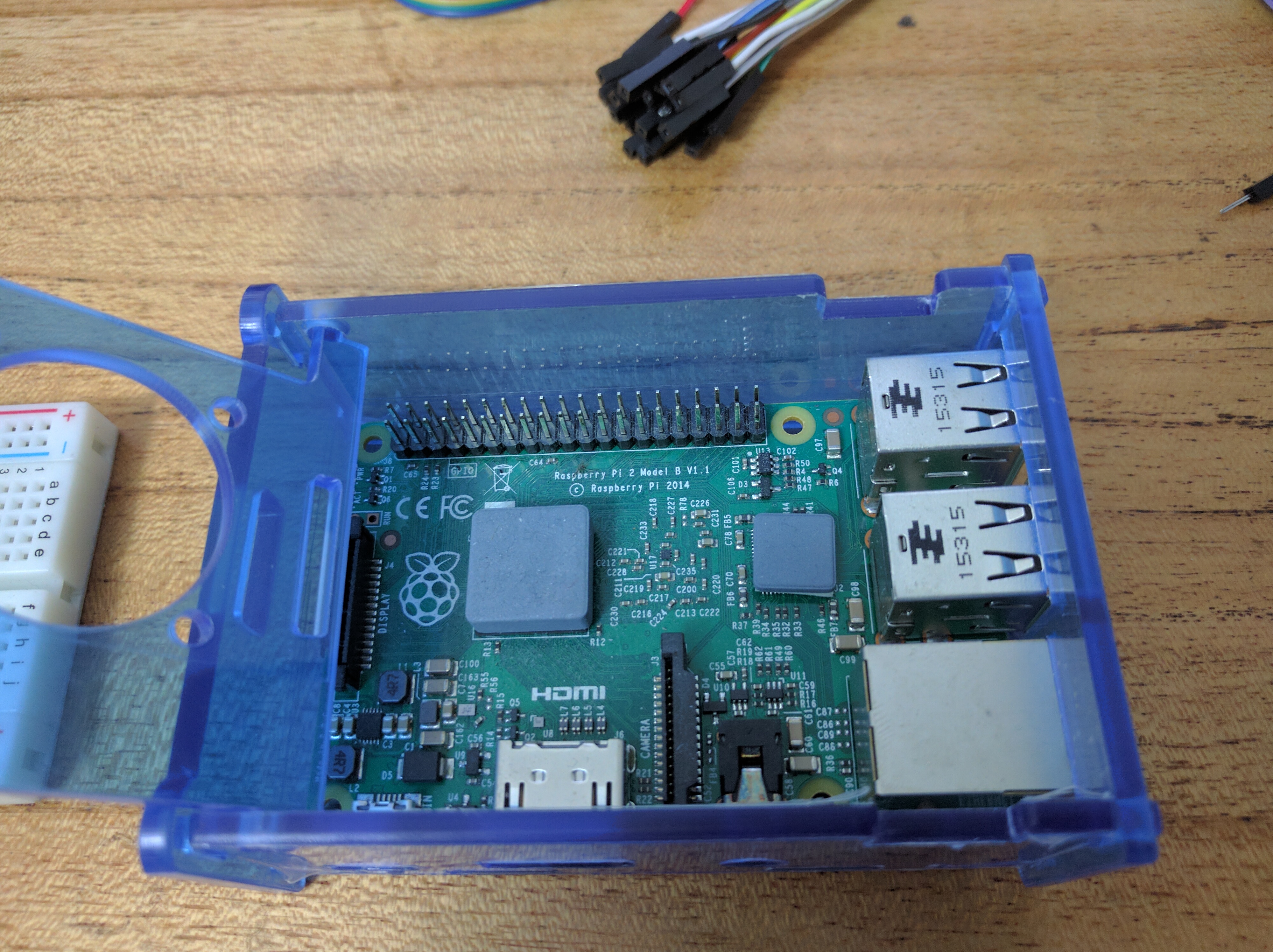
Know your Pi
The pins on the Raspberry Pi 2B are numbered from 1 to 40, but only a specific set of these are used to flash the BIOS. According to flashrom's documentation, these are the pins:
Pin 25 - GND
Pin 24 - /CS
Pin 23 - SCK
Pin 21 - DO
Pin 19 - DI
Pin 17 - VCC 3.3V (+ /HOLD, /WP)
And all the pins are:
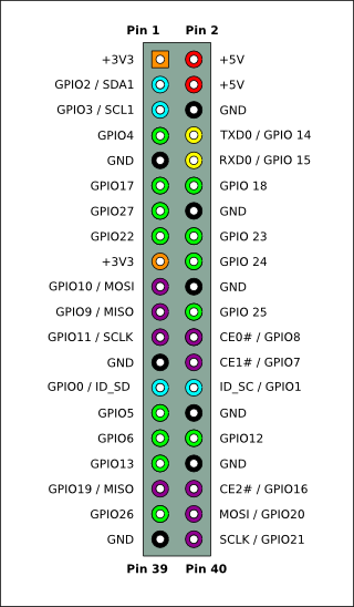
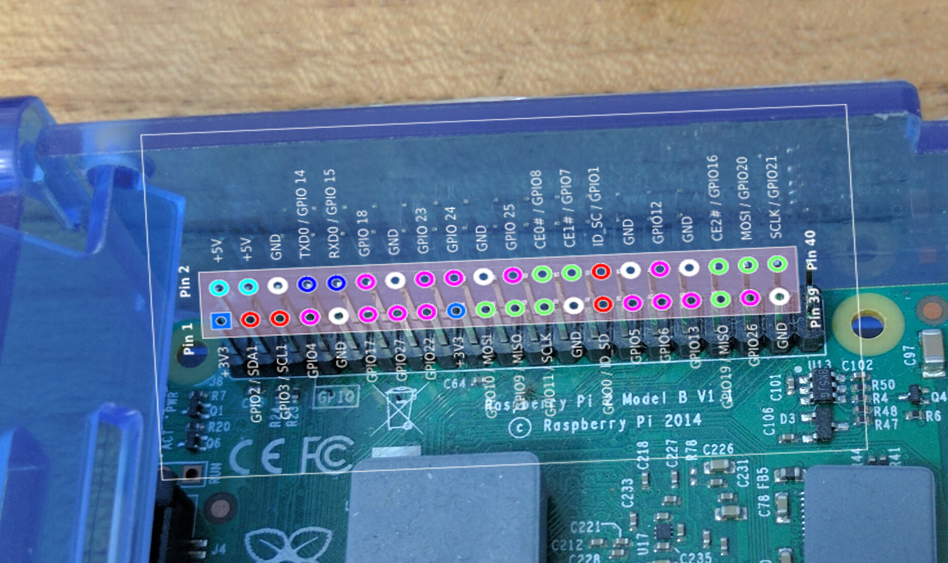
Which overlays on top of the earlier image like this for the Raspberry Pi 2 B:
Know your notebook
(Or your girlfriend's/boyfriend's)
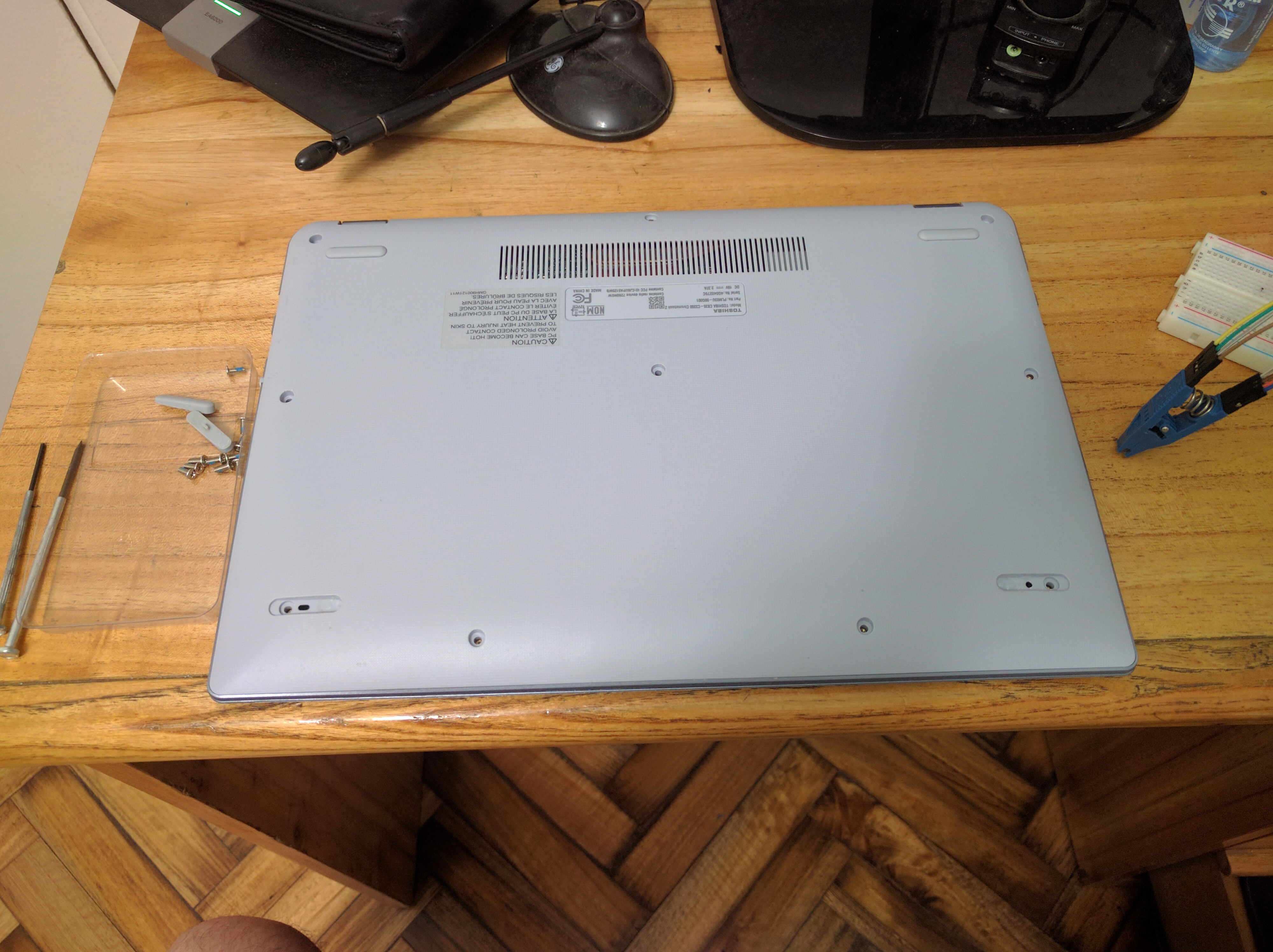
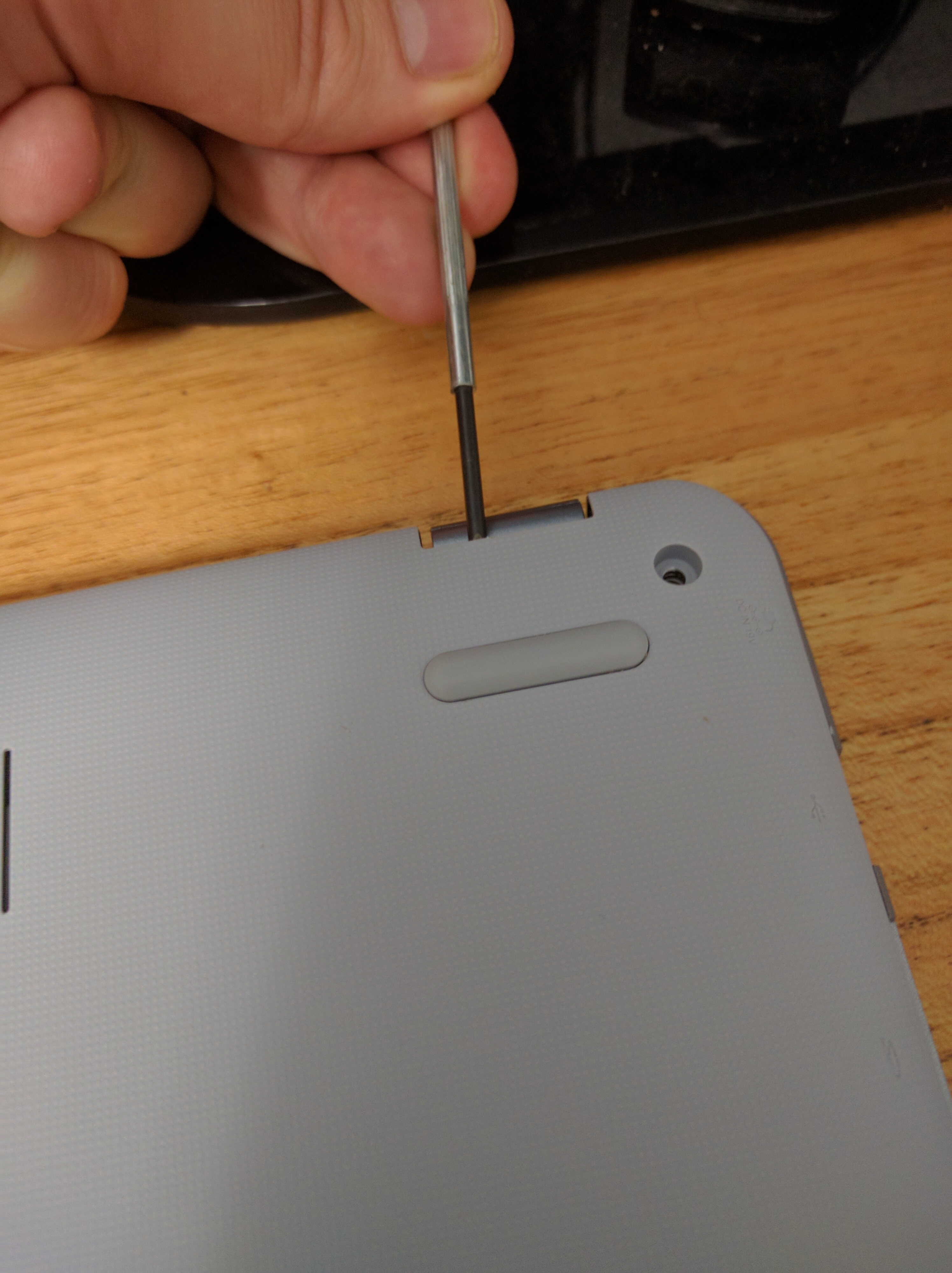
First of all, unscrew the bolts, and remove the back case. You probably already did this to remove the firmware write protection, that's how you got bricked in the first place right?
Before starting connecting anything, make sure that the battery on the notebook is disconnected, and the power cable is unplugged.
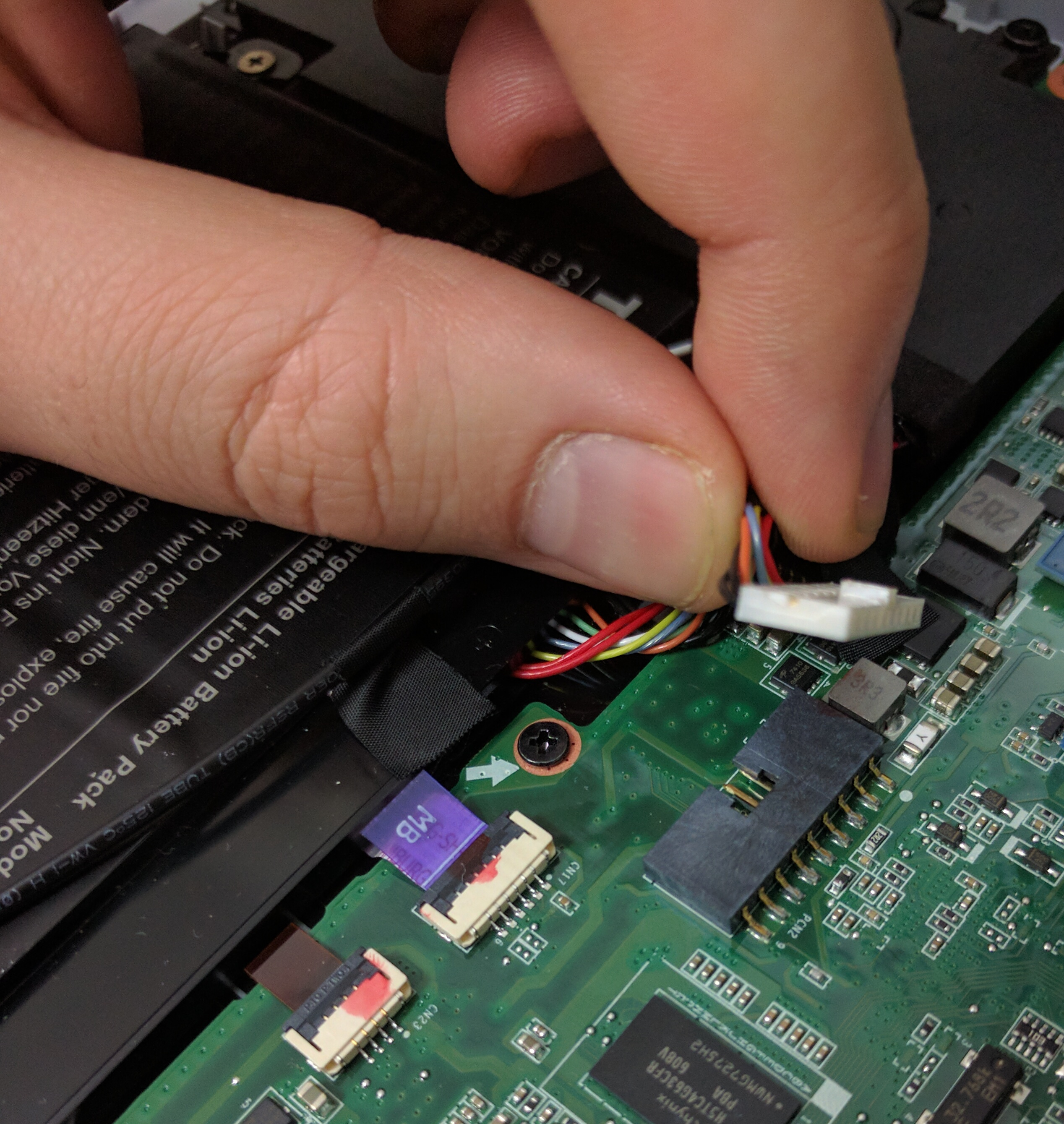
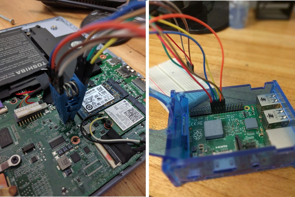
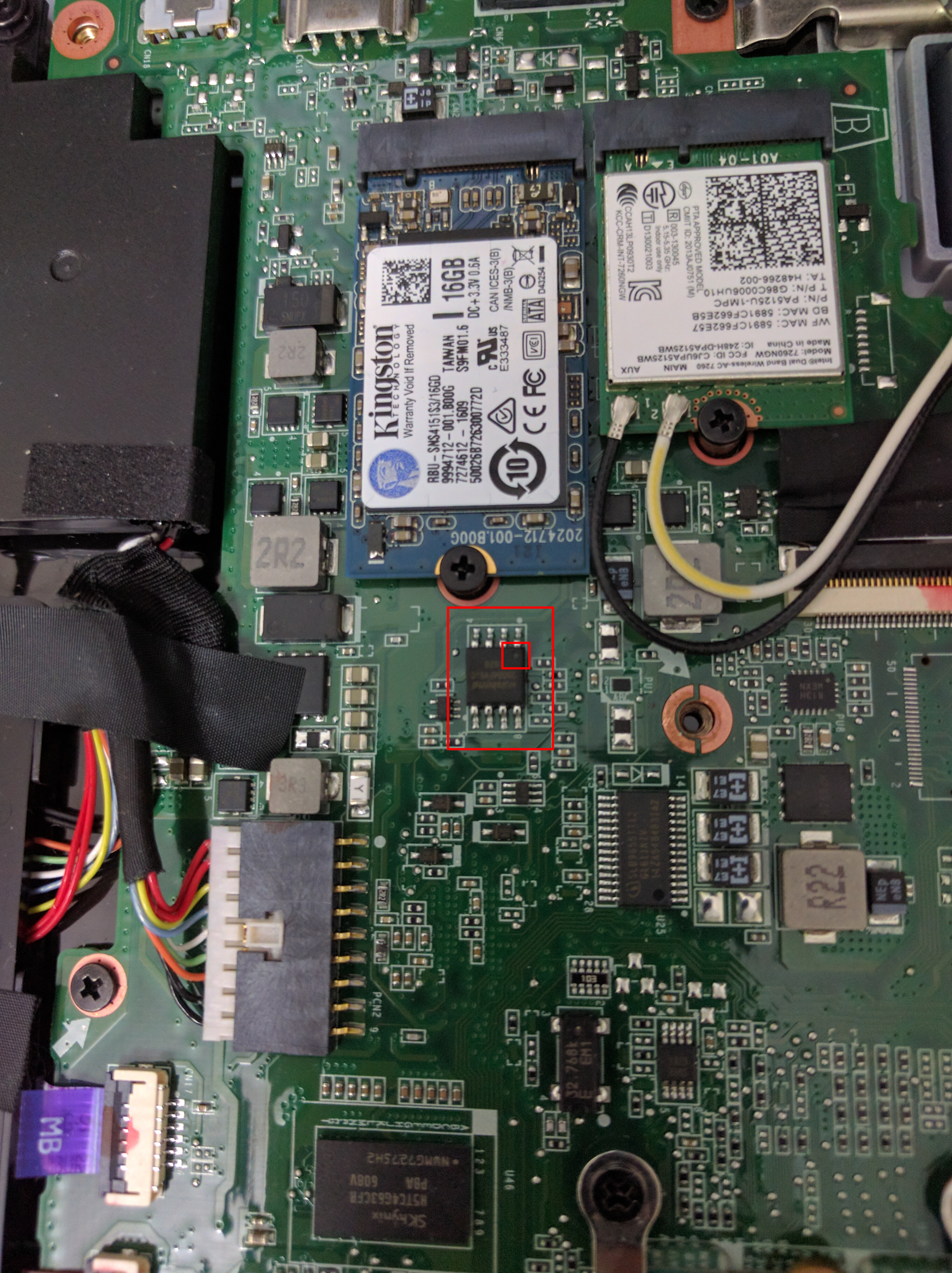
Identify where the BIOS is, and where is the dot that indicates where the CS pin is (Useful for knowing which way to connect the Sonoma Test Clip)
Start connecting stuff
Warning: Have all your stuff unconnected from any power source when doing this, or you could mess your chip irreversibly, also, be careful about correcting the right pins.
So, in summary:
- We need to connect Pin 17 to VCC, HOLD and WP.
- Pin 19 to DI
- Pin 21 to DO
- Pin 23 to SCK, which is named CLK on the manufacturer's spec
- Pin 24 to /CS
- And Pin 25 to GND
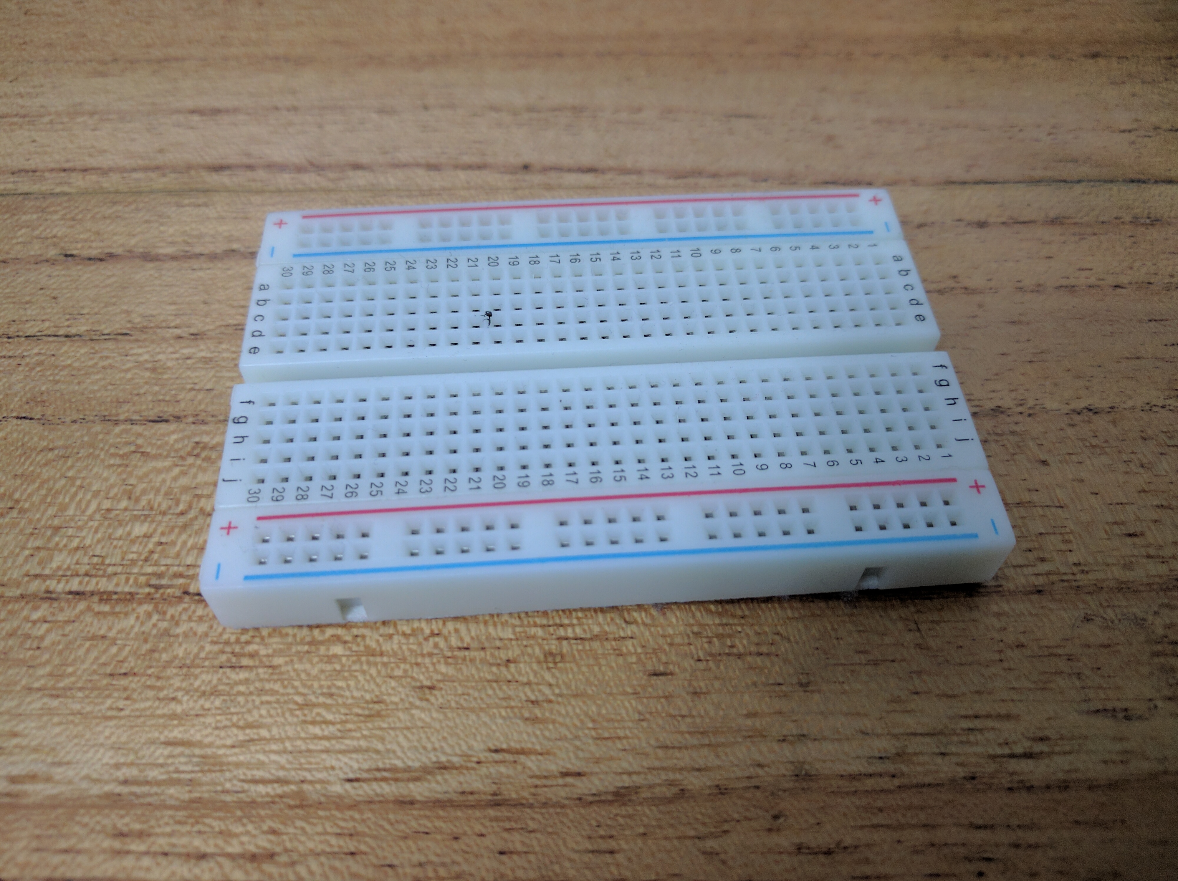
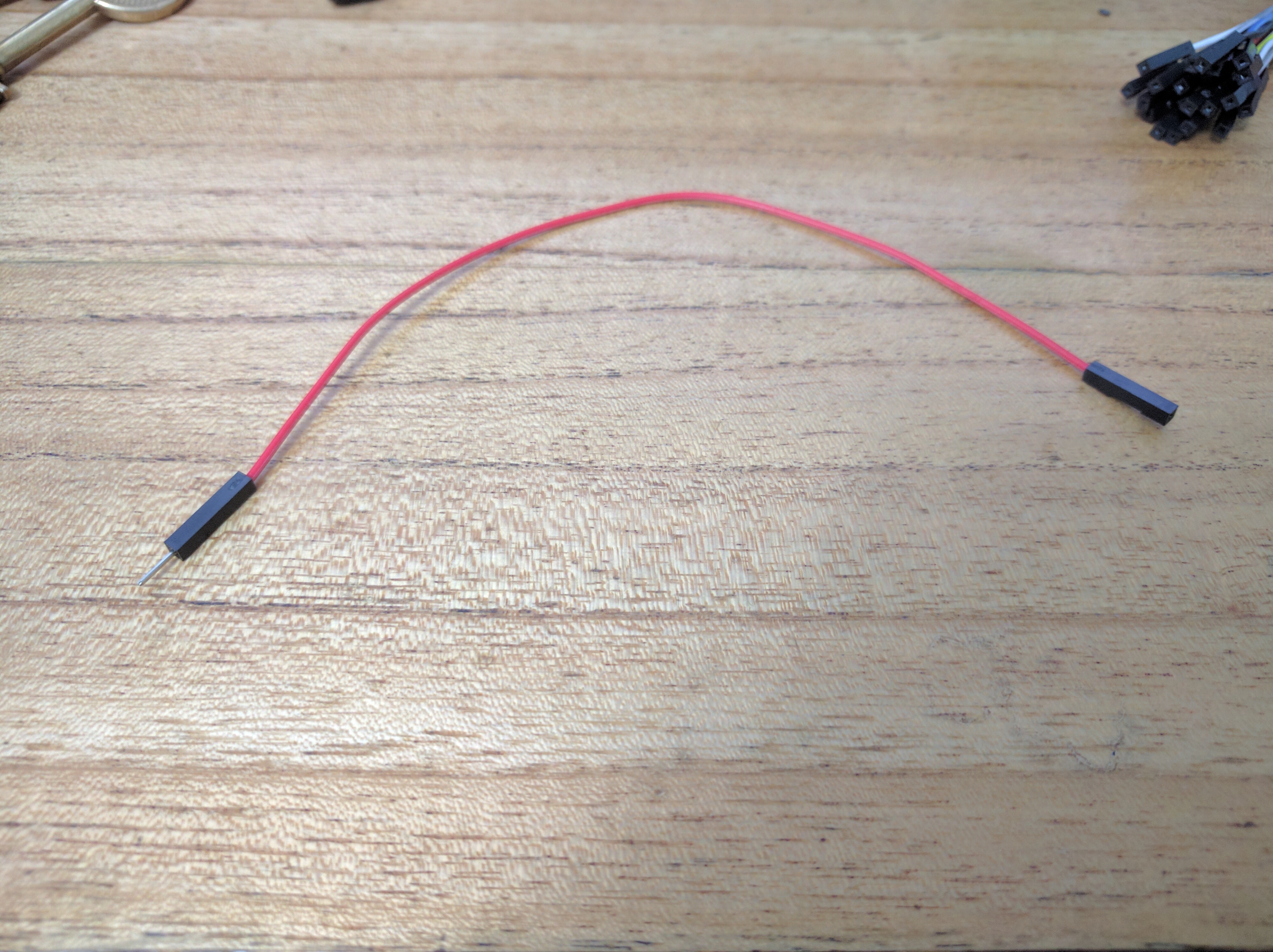
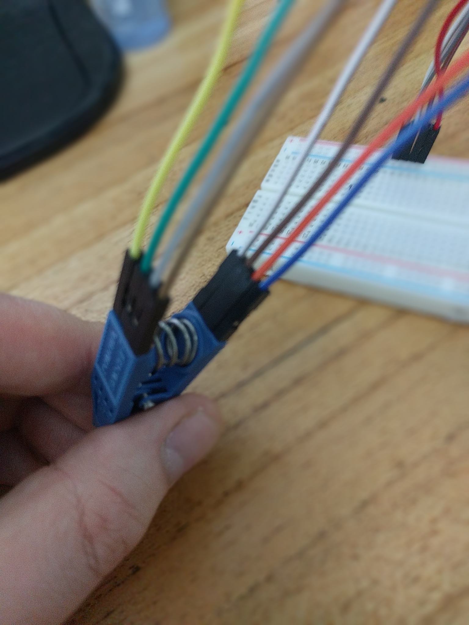
Sounds easy enough, just connecting some jumper wires, the only weird part is Pin 17, how can we connect 1 cable to 3? I've seen 2 solutions online, one is to short them together with copper wire, i suppose cutting and exposing the jumper wires would be the solution. I don't feel that confident with electronics, so i chose using a Breadboard i already have to do the connection. Here we need the Female to male jumper wires.
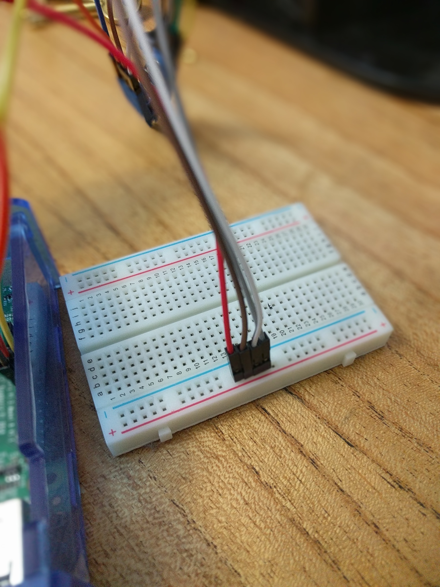
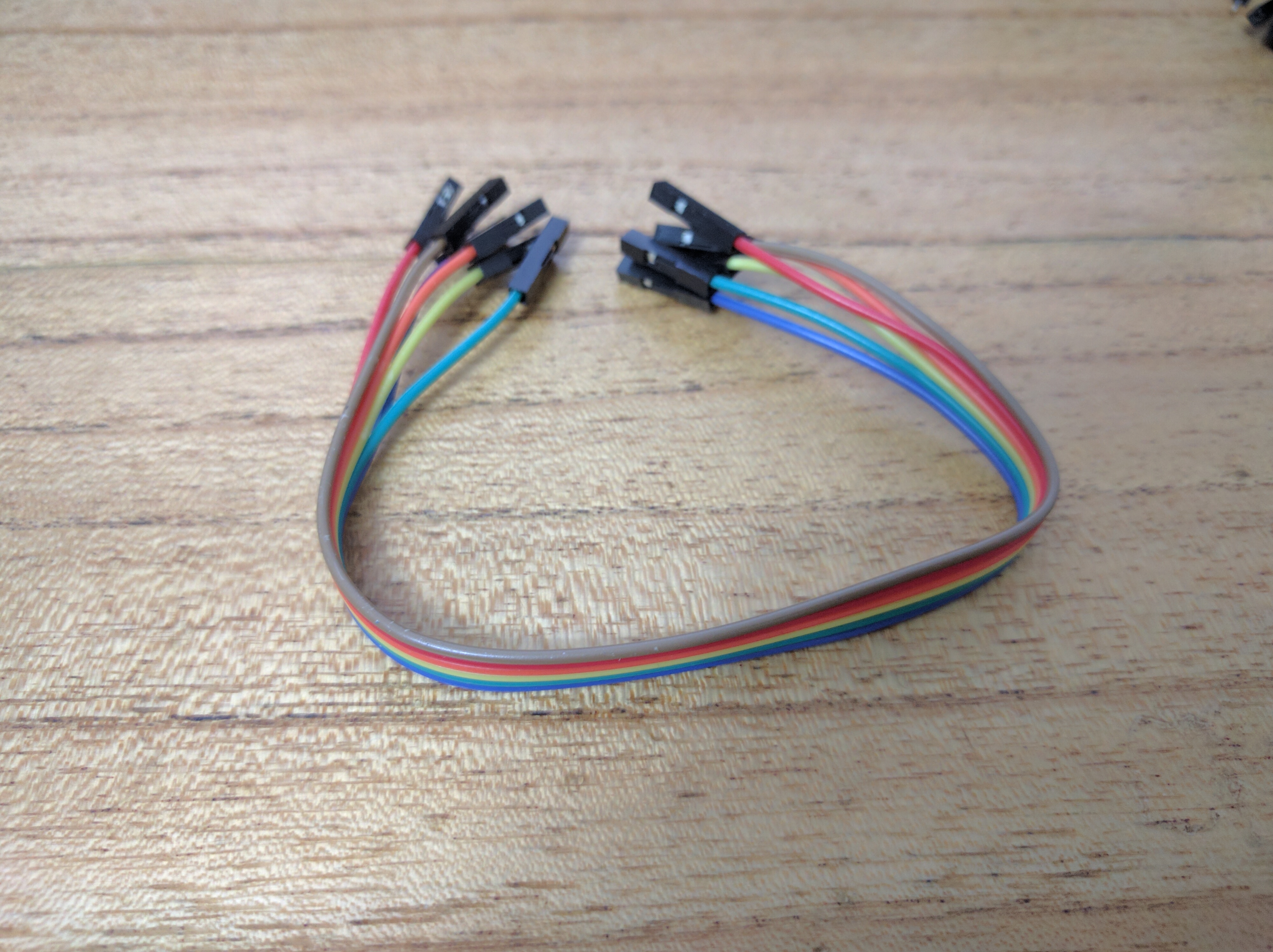
The other connections are simple by using the female to female jumper wires, when done, you should have something like this

On to the final step
So, you are very sure you connected everything correctly. You are very sure right? Make sure the clip is properly grabbing the chip, and that when you connect the raspberry you don't move the clip too much so it doesn't disconnect while you are flashing. I'm no expert but better be safe than sorry.
So, before trying to flash a new ROM, let's first save the bad ROM into our computers, for two reasons:
- Let's try first a non-destructive operation right? First read and later write
- If you want to report a misbehaving ROM, it may be useful to show the original developers the ROM that caused the issue, so he/she/they can check for any issues and avoid other people from bricking their machines.
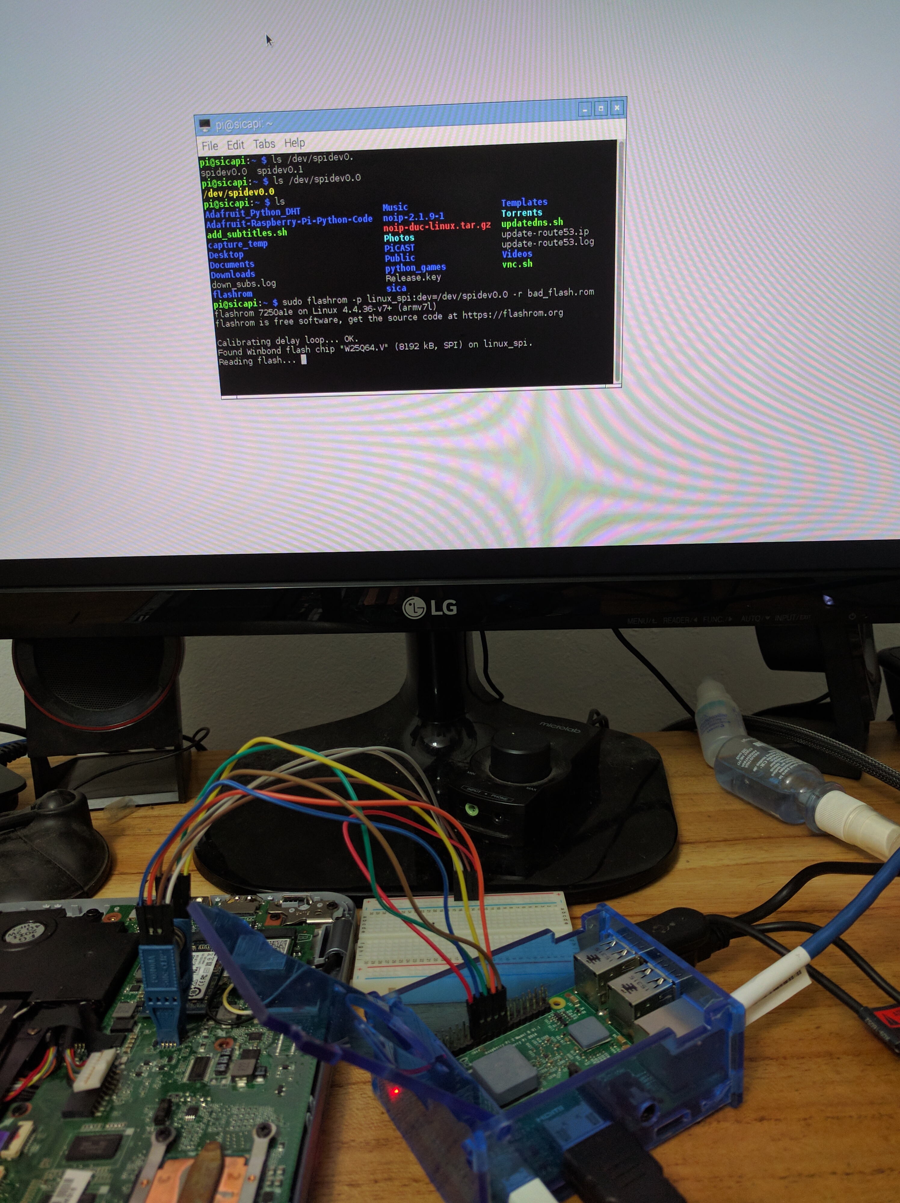
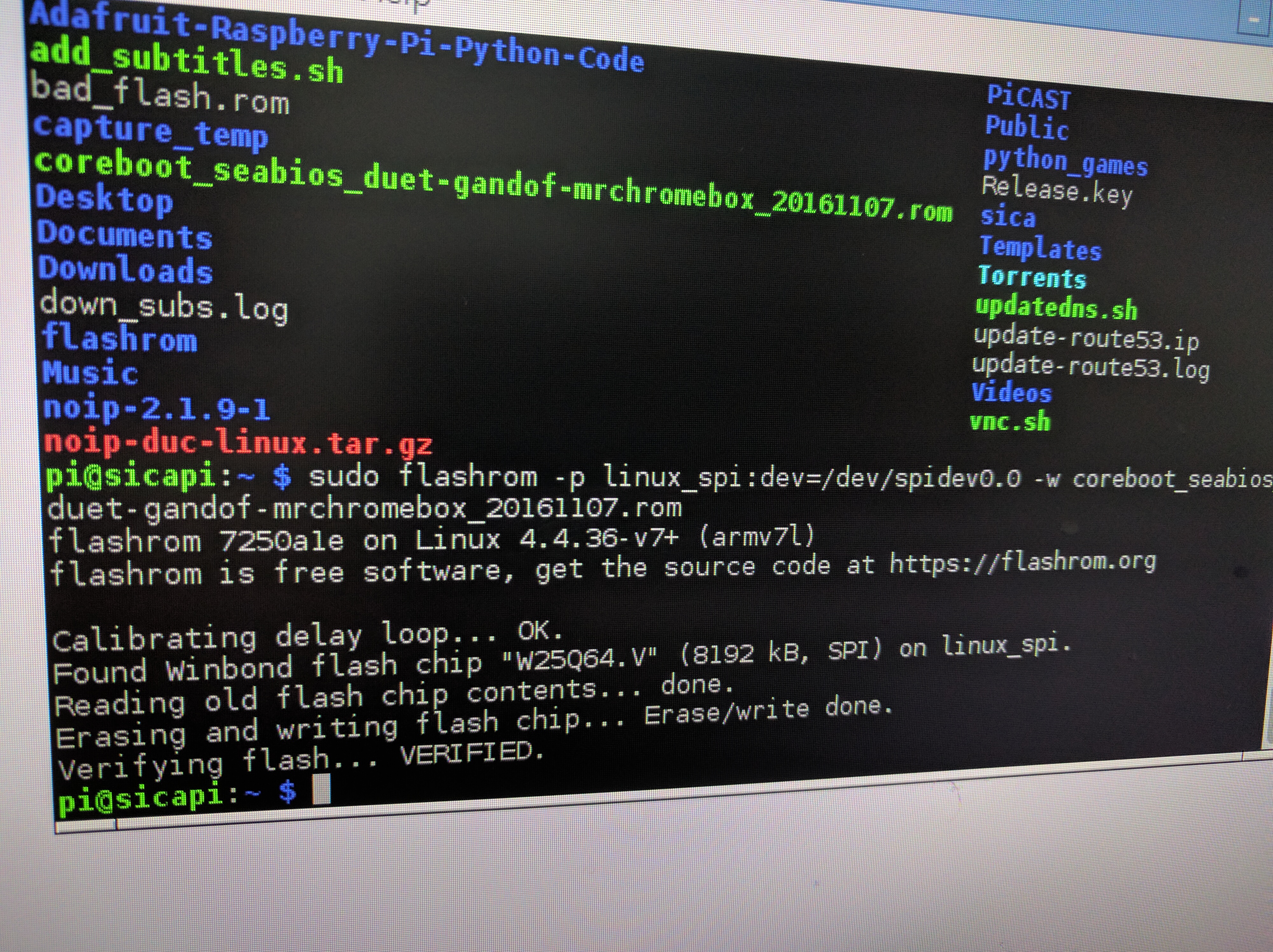
So, with everything connected, let's first run this command on the raspberry pi:
sudo flashrom -p linux_spi:dev=/dev/spidev0.0 -r bad_flash.rom
And then, let's flash the new one:
sudo ./flashrom -p linux_spi:dev=/dev/spidev0.0 -w gandof-stock.bin
It doesn't take as long as i had expected, i think it took around a minute for each operation.
Installing an OS
After all of this, the computer started booting again, and after installing a custom ROM which worked i could install an operating system on top of the new BIOS. I chose Linux Mint, it seems GalliumOS is not supported on a UEFI BIOS for now, but oh well, Mint works fine on this computer.
Just a quick heads up, to boot after installing you have to add to the boot manager the option with file EFI/ubuntu/grubx64.efi, which it doesn't find automatically. The one it looks for is EFI/BOOT/BOOTX64.EFI. So i made sure that was the path to get to grubx64.efi. I don't know why this happens but after modifying that it works perfectly.
If you don't love yourself (Or the notebook's owner) you could also install any flavor of Windows that supports UEFI.
As promised in the title, though we had to follow a lot of rituals, we didn't have to invoke any demons... right?
References
These are some of the wonderful online resources i used to compile this guide:


